Two heat pumps, one buffer and four months behind one terminal
RAKHEAT is a heating upgrade for a ~200 m² house in northern Estonia: a second
heat pump in cascade, all control moved into Home Assistant, and every decision made on
measured data rather than estimates. This page is an honest project log — including the
four-month dead end whose cause turned out to be one wire on the wrong terminal.
423–508 W/K
measured heat loss of the house — derived from hourly data, not from a designer's table
8 kW
primary pump capacity. It runs out already at 0 °C — the case for a cascade is proven
979
bus telegrams that produced a device-specific parameter list
14
entities in Home Assistant, including writable setpoints
01 — Starting point
A problem that repeated every winter
The house has been heated by an air-to-water heat pump since 2019. In winter it ran
essentially continuously and the 6 kW resistive backup joined in regularly —
the most expensive way to keep a house warm. The energy bills said the same thing.
The classic response is to buy a bigger pump. The first decision in this project was
the opposite: measure before you buy. How much heat does the house actually
lose? At what temperature does the existing capacity run out? Is a second pump the
answer, or just another machine that struggles the same way?
Measured, not assumed
How the heat loss was derived
Hourly electricity data from the grid operator × monthly mean outdoor temperatures.
Summer months give the base load that is not heating; the rest is heating energy per
degree-day.
# a result, not an assumption
base load (Jun–Aug)      16.4 kWh/day
heating per degree-day    4.06 kWh/day/K
heat loss (COP 2.5–3.0)  423–508 W/K

capacity needed   0 °C    8.9–10.7 kW
                −10 °C    13.1–15.8 kW
                −22 °C    18.2–21.8 kW
The primary pump delivers 8 kW. The number that made
the decision: capacity runs out already at zero, not at minus thirty.
02 — Solution
Cascade: two pumps, one buffer tank, one master
The newer, more efficient unit (R32) stays primary and handles both space
heating and hot water. The older unit is connected in parallel to the same 200 L buffer
tank and runs only as a second stage when the buffer falls behind its target. The key
control rule: only one device may decide what temperature water the house gets.
Click a block in the diagram
Every block explains what it does in this system and why it is built that way. Keyboard works too: Tab + Enter.
← scroll the diagram horizontally →
flowreturncontrol signal / data
Hydraulics
Parallel, not in series
Both pumps lift the same tank. Non-return valves prevent cross-flow when only one runs.
The tank also buffers, which reduces short cycling.
Control
One dry contact
The backup pump is started and stopped by a single potential-free contact on its
controller's external input. An existing smart relay made the hardware cost of this
zero.
Fail-safe
A failure leaves the heat on
Relay off or unpowered = backup pump allowed. A home automation failure cannot
leave the house cold — it can only leave it unoptimised.
03 — Try it yourself
Two tools running this house's real numbers
Both use the same formulas that run in the system — heat loss derived from
hourly data, the weather curve from 344 measurement pairs, and cascade conditions that are
one-to-one with the ones running in home automation. Move the sliders and watch.
How cold must it be before 8 kW runs out?
—
capacity needed
—
flow temp target
—
primary pump margin
•
Maths: Q = k × (21 − T), where k = 423…508 W/K
is the measured heat loss. Flow: 33.3 − 0.35 × T.
Honest caveat: 8 kW is the nameplate rating — real capacity drops in the cold,
so the actual shortfall starts even earlier than the chart shows.
Play the cascade logic through
Decision in real time
—
buffer target
—
deficit
✗
✗
✓delay 25 min elapsed · min run time 60 min
•
Worth noting: the primary pump's state is not in any condition. If it quietly
stops, that shows up as a buffer deficit and the backup comes in anyway.
04 — Dead end
Four months that ended with one terminal
Inside the older pump there is an industrial controller that speaks its own
bus protocol. There is an excellent open-source way to read it — a small board and firmware
that turn the bus into a web interface. The hardware arrived in April. Then came four months
of silence.
HYPOTHESIS 1 · MAY
Wrong firmware or wrong pins
The boot log said the telegram was being sent. So the fault must be where software
meets the bus. The configuration was checked line by line. All correct.
HYPOTHESIS 2 · MAY
The adapter board is the wrong way round
If software is fine, physics must be at fault. All four combinations of board
orientation and bus polarity were tried. Four attempts, four times “query failed”.
HYPOTHESIS 3 · MAY
Write access level is too low
A convenient explanation, because it would have been one menu item away. Checked —
the level was correct from the start. Measurement later proved the lock was never
about levels.
HYPOTHESIS 4 · SUMMER
The controller board is a cheap clone
An explanation that permits inaction: if the hardware is wrong, there is no point in
trying. A photo of the board's underside proved in September that it was genuine. By
then four months were gone.
25 SEPTEMBER · 17:05
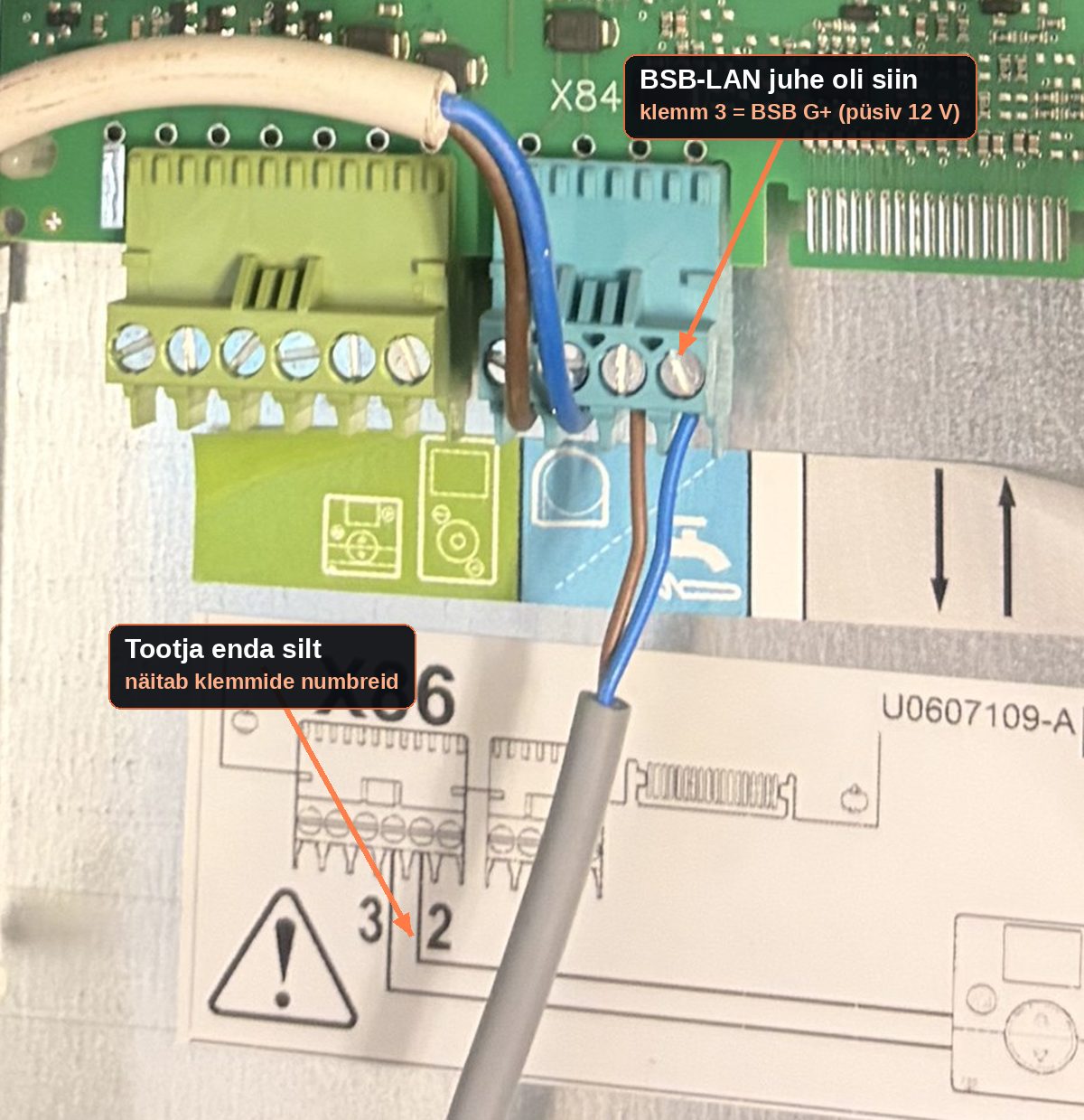
And then someone looked at the terminal
The controller's connector has three terminals side by side: data line,
ground and permanent 12 V for the wall unit's backlight. The data wire
was on the third. The device had power, the LED was on, the web interface answered —
and it was not connected to the bus data line at all.
RESULT
Wire moved one terminal
The answer came in seconds. Outdoor temperature 12.1 °C — and three independent
sources agreed. Four months were spent looking in software, because that could be done
from a warm desk; the one thing never checked was the most boring one.
01 firmware and pins
02 board orientation and polarity
03 write access level
04 cloned hardware
05 wire on the wrong terminal
A real photo from May. The fault was visible in this picture the
whole time — nobody read the terminal number.
Game
Put yourself four months back: what do you think was wrong?
This much was known: the board has power and its LED is on, the
firmware boots, the web interface answers, the device sends a query onto the bus — and no
answer ever comes. Pick one.
Why it took so long: every wrong hypothesis was plausible and each could be
tested from software or by turning the board — comfortably, at a warm desk. The only
thing not checked was the dullest one: is the wire on the right terminal?
“The LED is on” only ever means that power is present.
The best part: when the project's author was finally sent a description, he replied —
without knowing the fault had already been found — with exactly the same diagnosis:
“if the LED is always on, you have probably connected it to G+, which is no data line but
permanent 12 V.” An independent confirmation beats confidence.
The photos that prove this story
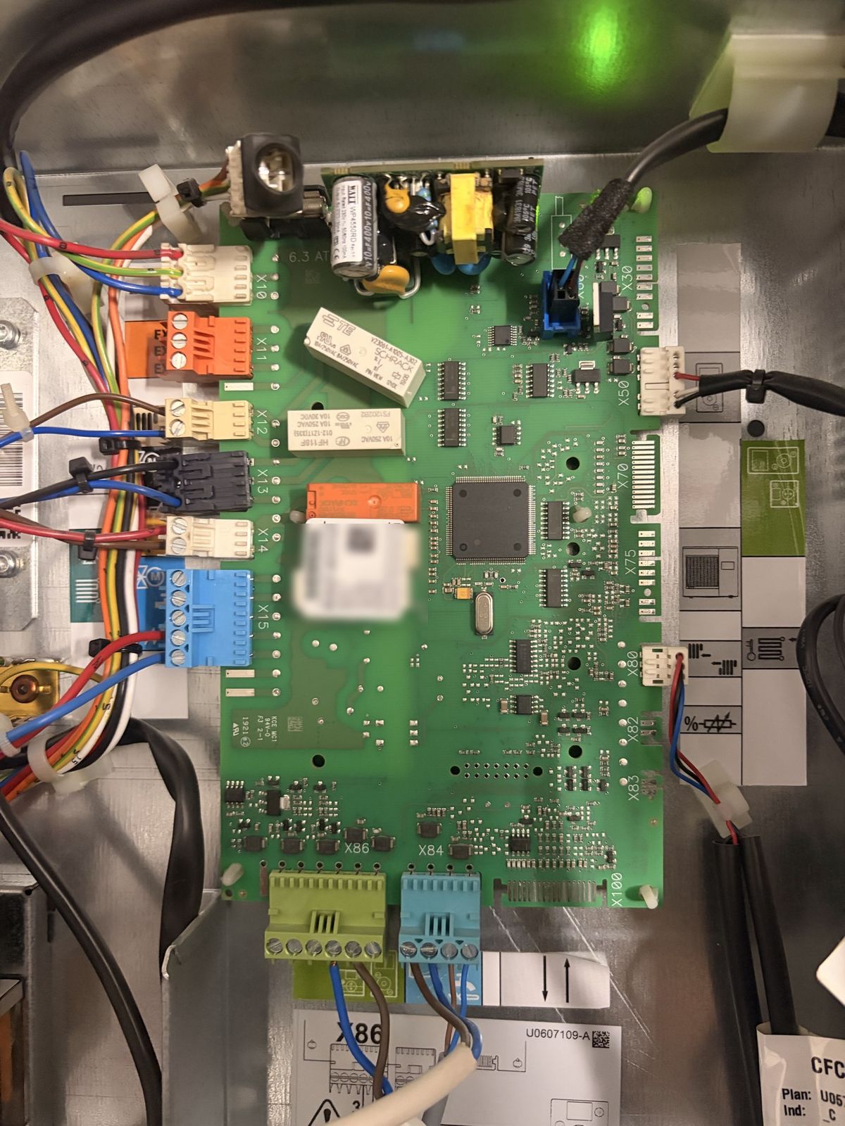
The controller board. Siemens RVS21.831/127, Series F, FW 8.5 — the very
device whose parameter list was missing from the open-source firmware. Orange
X11 connector on the left (external inputs), X86
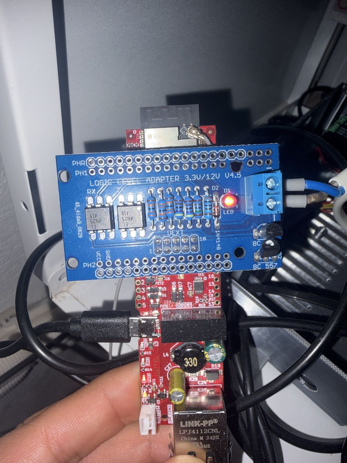
at the bottom, where the bus speaks. The serial number is deliberately blurred.The level adapter. Frederik Holst's board on an ESP32 — it turns the
industrial bus into a web interface. It is powered from the bus itself, with no separate
supply. That is what made the fault so cunning: power arrived from the wrong terminal
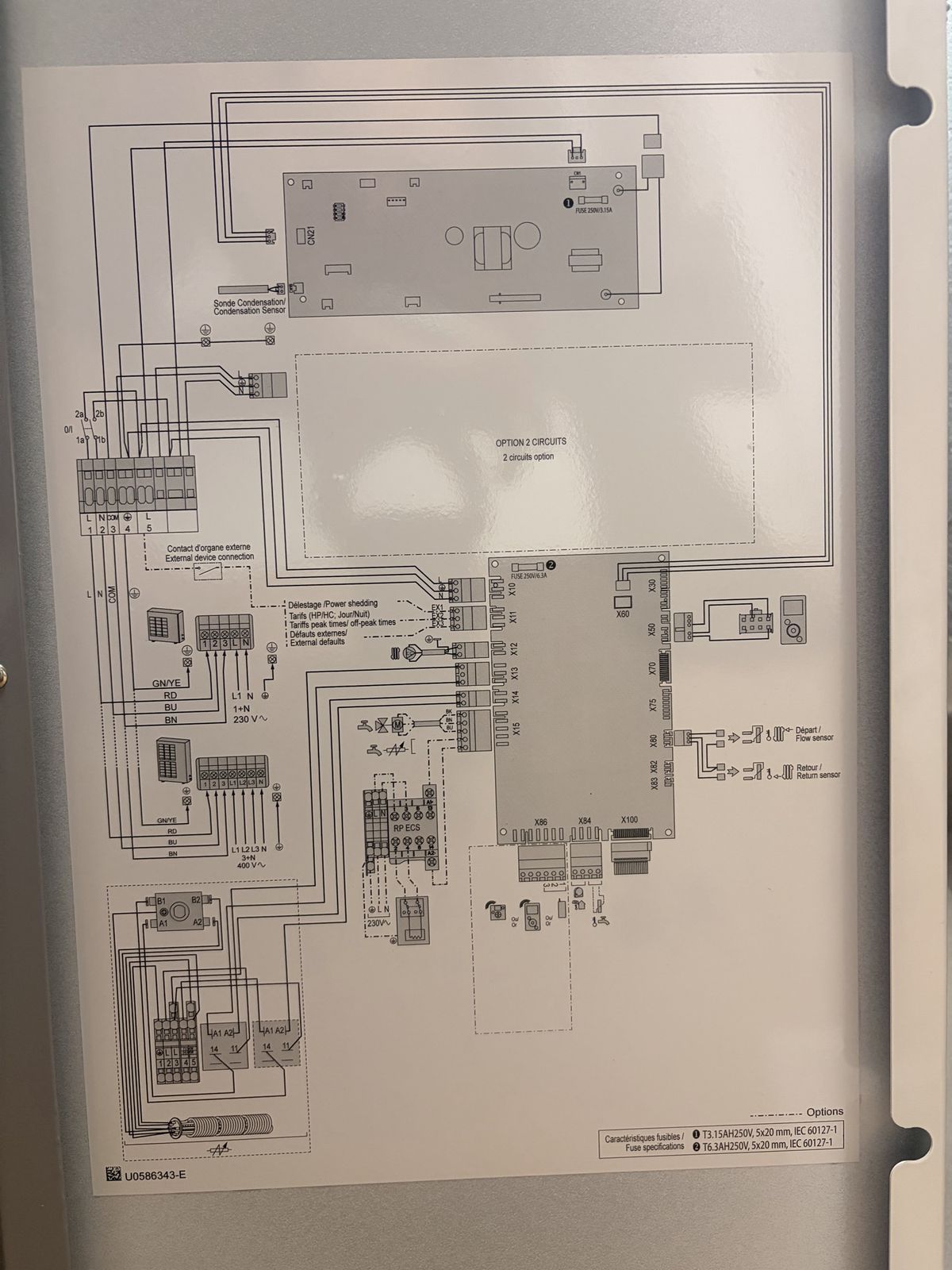
too.The manufacturer's wiring diagram. This sheet overturned my earlier
warning: the generic manual says EX2 is a high-pressure safety
switch, but the manufacturer's own diagram assigns EX1 to
“load shedding” — an external cut-off. The manufacturer's drawing wins.
The verification rule that came out of it
“The device does not answer” is a worthless conclusion unless you
also show that another device answers under the same conditions. Every later
measurement in this project comes with a control test — and three independent sources
eventually gave 12.1 · 11.9 · 12.0 °C for the outdoor temperature. Only then was the data
worth believing.
05 — Breakthrough
One day, six steps
25 September began with a four-month dead end and ended with heat pump
setpoints writable from home automation. All times are from the same day.
replay — from the real log, 25.09.2026
16:27
A request for help to the project's author
Boot log, the telegram sent, every combination already tried, and photos. The question was phrased to be checkable, not as “it doesn't work”.
17:05
Root cause found on site
Comparing the terminal drawing with the actual wiring: the data wire sat on the power terminal. Wire moved → the bus started talking. A follow-up mail went out so the author would not waste time.
17:42
Full scan and parameter dump
979 telegrams. It turned out setpoints were unwritable not because of the device but because of the firmware's parameter table: this controller model was not in it.
18:03
The author sent a converted parameter list
962 entries, built from our dump. Before installing it, both required parameters were verified to be present and free of the read-only flag.
23:05
Firmware updated and list installed
Firmware 15 versions old was replaced with the newest. The update was deliberately done on site over USB, because the release changed the settings memory layout — the wrong choice would have meant a dark device in the basement.
23:40 → 00:00
Messaging up, setpoints writable
The device publishes its readings every minute; home automation created 14 entities by itself, including writable ones. The first command back: the heating circuit mode was set to automatic — from home automation, not from the device's own panel. The confirmation was read back from the device itself.
06 — Measured results
What is different now
What
Before
Now
Backup pump telemetry
none at all
whole bus readable, readings every 60 s
Changing setpoints
only the device panel in the basement
from home automation, confirmed by read-back
Weather curve
unknown, installer menu did not show it
derived from 344 pairs: 33.3 − 0.35 × T
Hot water cycle
30 ↔ 56 °C, 3.5-day period, lukewarm half the time
stable 50 °C, hysteresis 25 → 8 K
Visibility of resistive heating
discovered on the bill
own sensor + phone alert within 2 min
House cooling down
you noticed when it got cold
drift watchdog warns on a 6 h trend
Cascade logic
a plan on paper
live: relay on the EX1 input, the automation releases and blocks the backup pump by itself
Logic
How the cascade decides
# buffer target comes from the primary pump's MEASURED curve
target = 33.3 − 0.35 × outdoor
deficit = target − buffer actual
# the backup is released when:deficit > threshold (3 K) ANDoutdoor < bivalence point ANDdelay elapsed (25 min)
# and blocked again only when the need is gone# AND the minimum run time (60 min) has elapsed
A deliberate choice: the primary pump's state is not
part of the condition. If it quietly dies, that shows up as a buffer deficit and the
backup comes in anyway. The logic does not depend on a device being able to report its
own failure.
Honest limitation
The cloud said “OK” and did nothing
The primary manufacturer's cloud API accepts a setpoint write, answers
200 OK and leaves the device untouched. You cannot see this until
you read the value back from the actual device.
That produced a rule which is now in the code: every write is verified 40 seconds
later, and two silent failures in a row switch the automation off by itself and send
a notification. Better a standstill than false confidence.
Correction from October: the prediction written here —
“the cloud stays read-only” — turned out to be only half true. The setpoints are
read-only; the weather-curve offset is measurably writable through the cloud. So
when the bus bridge goes quiet, control falls back to the cloud and keeps writing from
there — slower and with a daily quota, but the house is never left uncontrolled.
07 — Working principles
Five rules that have been paid for
1. Measure, don't assume
Heat loss, weather curve, cycle period, cost — every number here is derived from data. Where there is no measurement, it says “unknown”.
2. A control test comes with it
A negative result only counts if you simultaneously show something that does work under the same conditions.
3. Writing is not confirmation
The command went through ≠ the device changed. Always read back from the device itself, not from the interface's optimistic state.
4. Watchdogs live in the system
Alerts belong inside home automation, not in a script on someone's laptop. That way they survive reboots and holidays.
5. Failure must be warm
Every automation's default state is “heating allowed”. Optimisation is a bonus; a warm house is a requirement.
+ Document with evidence
“Done” without a measurement or a commit is not done. Every change is in the log together with the numbers that prove it.
08 — October
The switch is on now
At the end of September this page closed with “the saving is calculated,
not yet earned”, and the spot-price switch was deliberately off until the write
path was proven. On 30 September the bus bridge arrived. The write path is proven, the
switch is on — and the first real numbers say something the model did not.
A local bus bridge, no cloud
The P1P2MQTT bridge was wired to the Daikin's X5M terminals
11 and 12, in parallel with the existing controller. It is powered from the bus itself.
From that moment, the weather-curve offset is written straight to the bus rather
than through the manufacturer's cloud.
12 s
bus write confirmed by the device. For the cloud the code waits 40 s, because the unit refreshes it with a delay
156
new measurements the cloud never gave: compressor power, flow rate, water pressure, COP
fallback
the cloud stayed. If the bridge goes quiet, control falls back by itself — and says so
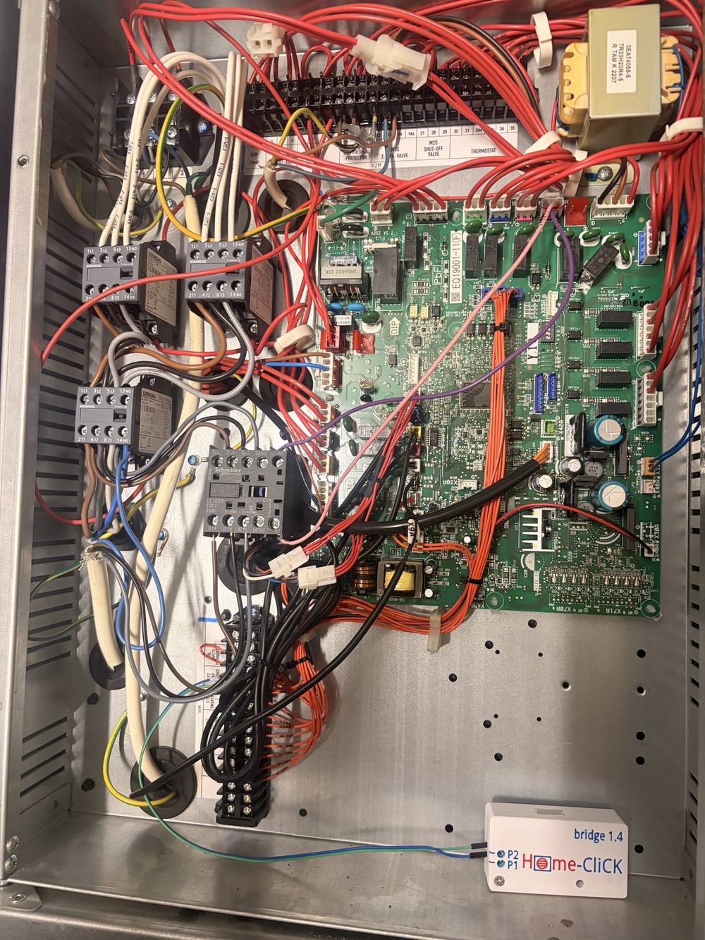
Bridge in the box. White enclosure bottom right, two wires to
X5M terminals 11 and 12. The upper terminal block
X2M is 230 V — pump, valves, thermostat — and that wire
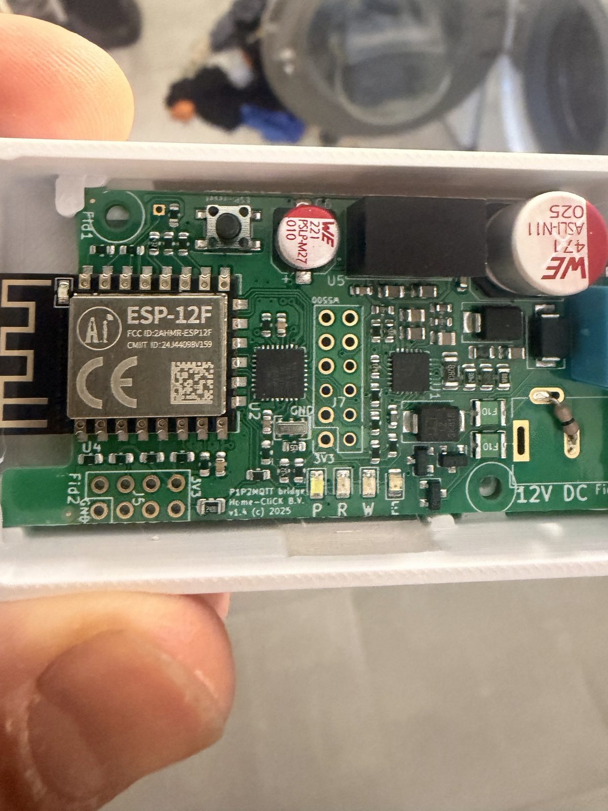
does not go there.The board. ESP-12F and P1P2MQTT bridge v1.4. Four LEDs show bus,
radio and writes. The device raises its own access point if WiFi disappears — which
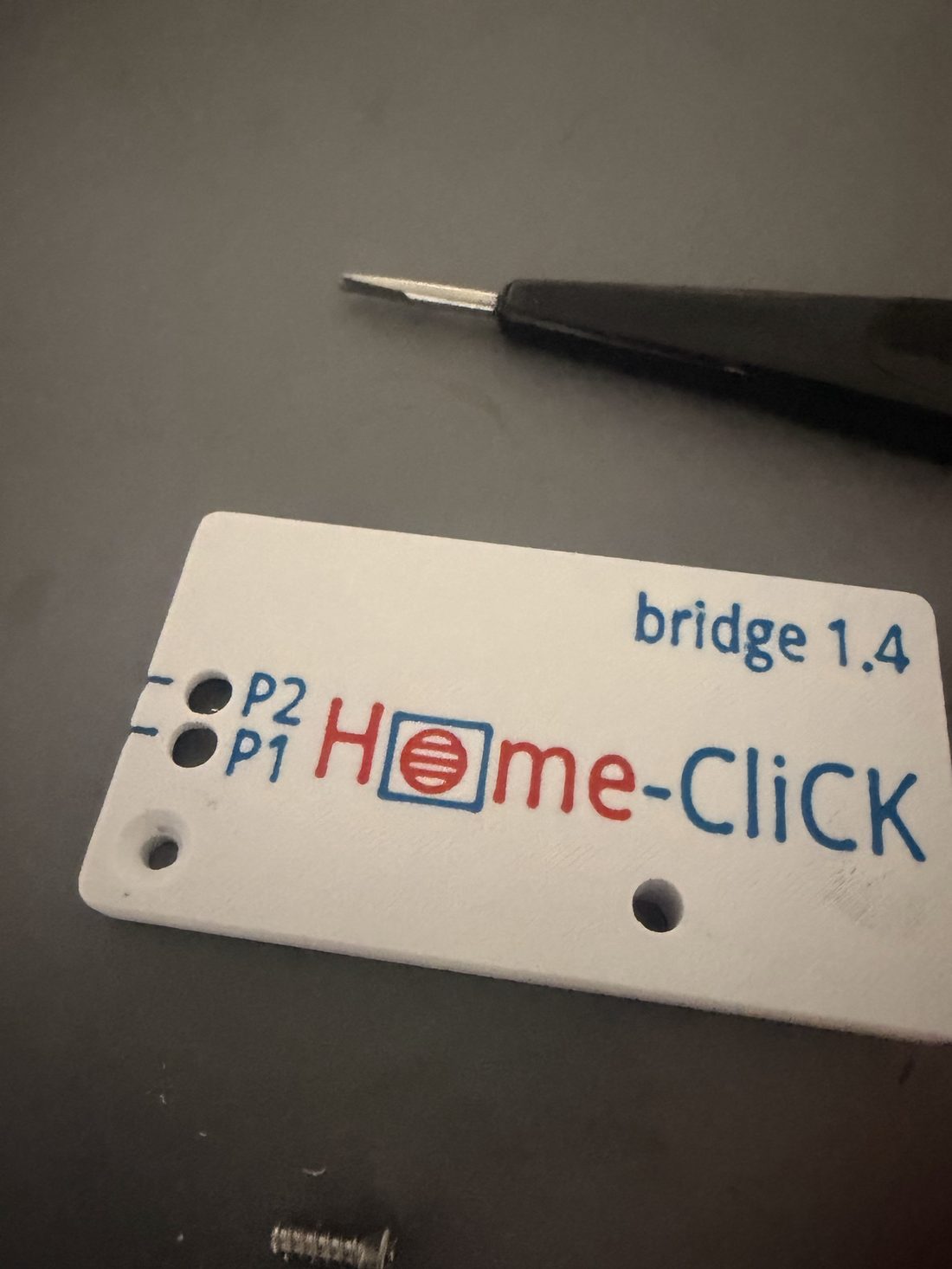
turned out to matter later.Two terminals.P1 and
P2 — polarity does not matter, but the fact that this is a
data bus and not a power line does. That exact distinction cost four months in the
previous chapter.
And then we measured what came of it
The model promised €342–514 per year from spot-price shifting. When the switch went on,
I built a measurement that compares the same day's same quantity against that
day's average hourly price — because that is the only part control can influence. The
result was uncomfortable:
Where the saving comes from
7 days
Year
Timing within the day
−€0.44
−€20
The equipment itself (old pump → new)
+€0.55
+€97
Total
€0.11
€77
Why timing was negative
Not because the offset was small, but because reducing was never allowed during
expensive hours. The comfort floor was 20.0 °C and one room — the ground-floor WC —
measured below it 88% of the time. Half the mechanism was silently disabled.
After the ceiling went from ±2 to ±3 K and the floor dropped to
19.5 °C, the offset moved 3 K in the right direction during an expensive hour for
the first time — and that room still held 19.3 °C overnight, warmer than the previous
week without any control. A month or two will show whether that turns the timing number
positive.
Three things measurement said and a guess would not have
The pump is second-hand
The unit's own counters: 17,879 compressor hours and 75,363 kWh of heat
produced. That is close to four seasons — from a previous installation. A lifetime COP
of 4.49 is therefore not this house's number, and it did not go into the model.
A separate measurement runs from zero.
The meter was on the wrong phase
The new current meter showed the compressor negative and at half size. A power
factor of 0.41 gave it away: cos 120° = −0.5 —
voltage and current were on different phases. I nearly “fixed” it with a software flag
that would have left a silent 2× error in place.
The backup heater won't start
A load test demanded 55 °C flow temperature. The compressor went to full power, the
temperature stalled at 37 °C — and the 9 kW electric backup never came on. At
+11 °C outside the unit simply refuses. Worth knowing before the bill says it.
Watchdogs that paid for themselves
On the evening of 2 October both heat pumps vanished at once. The house had power. The
first diagnosis — mine — was an electrical fault, and I sent the owner to check the
breakers. That was wrong. The cellar WiFi node was down and all three devices sat
behind it; the pumps themselves ran on their own weather curve the whole time.
The evidence was in my hands and I did not use it: the house cooled at −0.09 K/h both
before and after the outage. Had heating actually stopped, that rate would have increased.
What was built from that
The watchdog no longer says “bridge is quiet” but why: a separate ping per
network node, and the alert states plainly “the pumps are running, no need to check the
breakers”. Four states, all four tested.
And in October the deployment gate rolled back my own mistake
four times — three of them the same trap, where an entity's name and the
reference to it drift apart (across the whole project that trap has now repeated six
times, but the first four happened before the gate existed). Each time it rolled the
change back before it reached the house. A gate is not built to look good; it is built
to say “no” when you are in a hurry.
What is still on the table
The second current meter for the backup pump — the first is in and calibrated, the second is waiting
This house's real COP — counters zeroed on 2 October, the first honest number arrives in a week
Turning the timing number positive — ceiling and floor are changed, now it has to be measured whether that was enough
The cellar WiFi node — weak signal three times in three days. The watchdog covers it, the cause is open